Supercars
Jeep Hurricane

Feb
A design study on the revolutionary powertrain of the Jeep Hurricane.
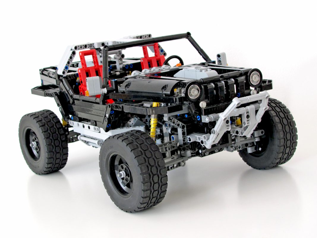
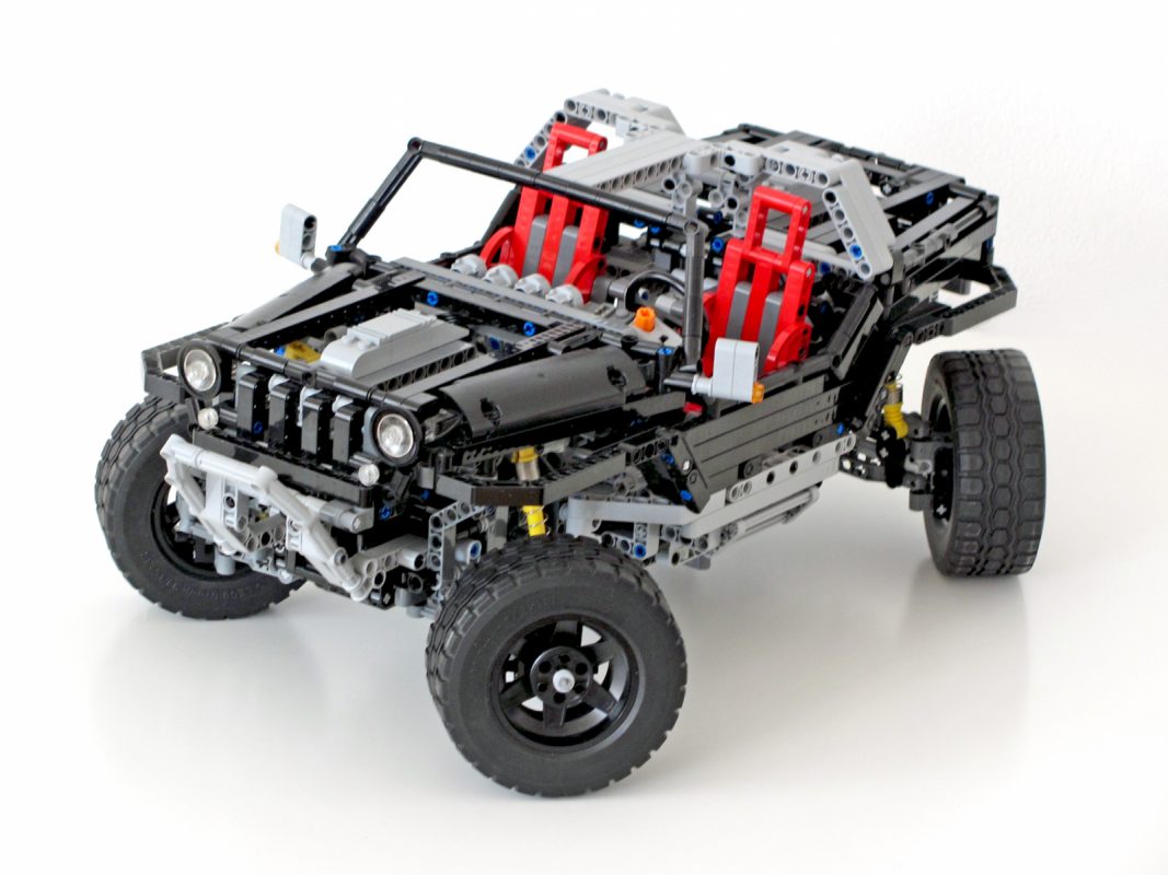
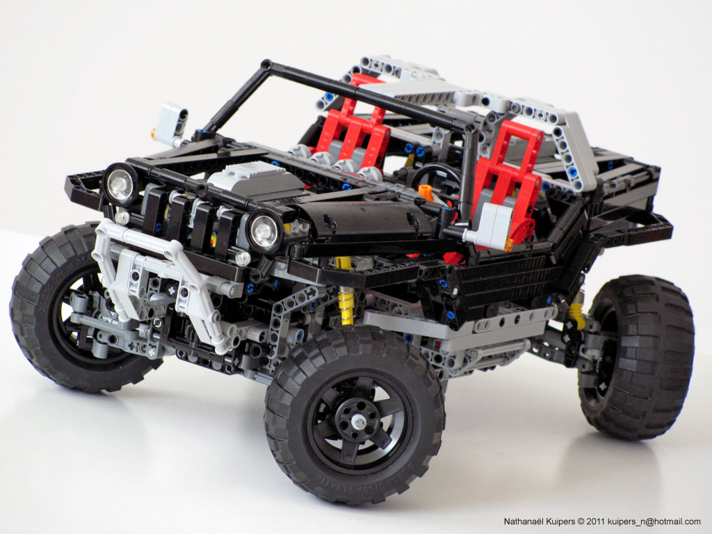
Features
- – All wheel drive
- – All wheel steering
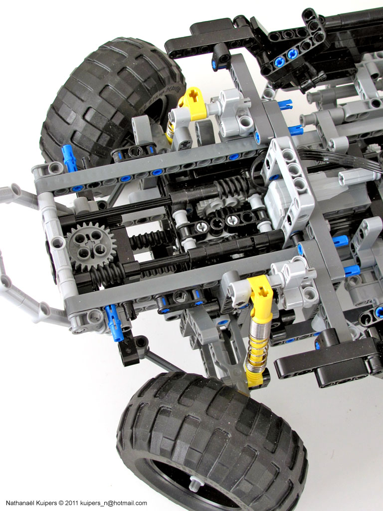
- – Full independent suspension
- – Skid steer option
- – Zero degree turning option
- – Double V8 engine
Background
In 2005 Jeep presented their ultimate Offroad vehicle on the Detroit motor show, the Jeep Hurricane. With 2 HEMI engines, all wheel drive, and all wheel steering, this machine could drive anywhere. Of particular interest was the zero degree turning radius option, with all wheels turning inwards in a circle configuration and the transmission changing from normal drive to skid steer drive. This fascinating phenomenon is normally controlled by complex electronic systems, but I wanted to investigate if something similar could be achieved mechanically using LEGO Technic.
Process
Because the real Jeep Hurricane is a technical marvel, I wanted to design the LEGO version in a similar spirit. Of course the zero degree turning option with skid steer had to be integrated somehow as this is the unique feature and characteristic of the real vehicle. The challenge however was how to combine this with the ‘standard’ 4WD and 4WS. An option would have been to power the left and right drivetrain and steer each wheel independently, but because that was already done by ‘Coney’ I wanted to do something differently. The problem also with steering each wheel independently is that they easily end up misaligned, unless there are some electronics behind it like in the real Hurricane.
So my first question and challenge was if it would be possible to solve the problem of the different wheel configurations mechanically in such a way that all the wheels are related and connected with one another in all positions, not forgetting that they also needed to be individually powered and suspended.
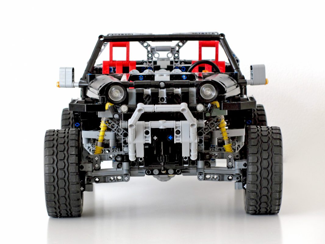
For the standard steering mode, having the position of the left and right wheels connected with each other, the easiest was to use a gear rack.
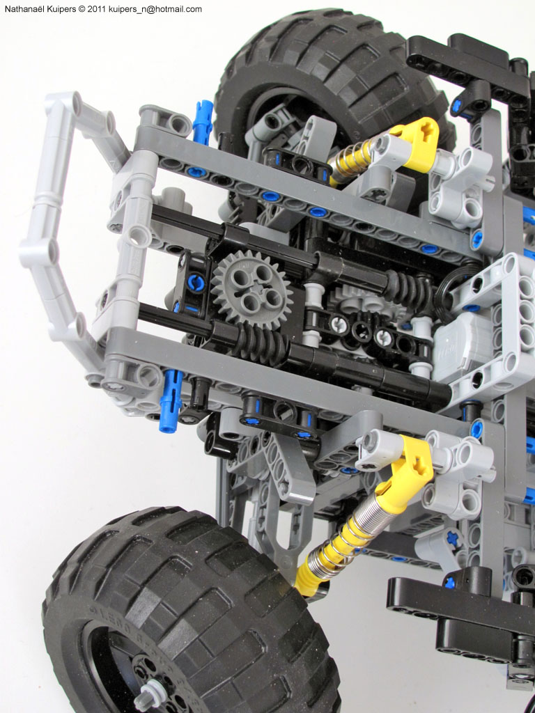
I also knew that by moving the whole gear rack away from the wheels, they turn inwards. This had to be achieved by a controlled sliding motion for which again gear racks were used in combination with a worm wheel. A linear actuator could have done the job here as well, but they would have been too big.
Once there was a working prototype of one of the axles, I had to build another one, which was a great opportunity to see if things could be simplified and built more compact.
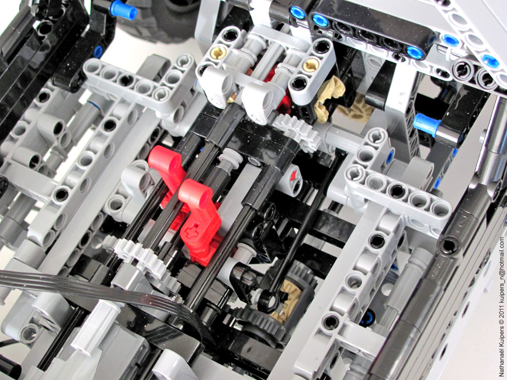
The next challenge was to find a solution for switching from normal drive to skid steer drive, using only one input. In any case it was necessary that the left and right drive train are separated, which should either work synchrone or in opposite directions. To achieve this the first idea was to be able to switch between odd and even number of gears in between the drive trains. Although there was a working concept it had certain drawbacks, one of which was the lack of a central differential which was not very realistic. So then the idea came up to use the differential itself as part of the switching function. Either power the central differential so both output axles go in the same direction, or power one of the axles as input and block the differential, so the output axle has to turn in the opposite direction. Because this meant that the smaller gears in the central differential play an important role and had to deal with some high stress I added another gear in the end to form a couple.
So now I had two working concepts, one for the different steering modes and one for the different drive modes. The next step was to integrate both in a single chassis. It was important to keep the distance between the front and rear axle as short as possible so it had the best chance of working. Preferably the model should be able to carry some motors too, which meant that space was very limited. Therefore it took some redesigns before I had solved all the interference between the different moving parts. Unfortunately this also meant that one of the differentials had to move further back, giving one of the axles more leverage to twist.
After the chassis with drivetrain was done, it was now time to connect the different steering configurations of the front and rear axle. The thought was again to use a switch for selecting a configuration and use a motor to put it in action. The central lever for switching the drive train in the chassis didn’t leave much room for both a motor, and the switching function of the steering modes. Besides a possible misalignment, this lack of space was the final reason to leave out the crab steering mode. I still needed to reverse the direction of the input axles of the different steering modes somewhere in between the front and rear to make sure that the result was correct.
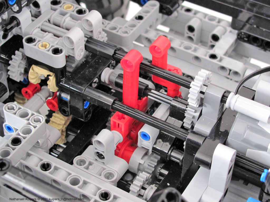
On top of that the drivetrain had to be connected to, a couple of V8 piston engines in both front and rear, which meant a lot of other gears and axles had to go through the center of the car as well.
With so many things depending on one another, a change at this point would have major consequences so from now on it was just a matter of fixing the center console together to see if the whole concept worked…
One could say that the concept was proven with all the different configurations, but unfortunately the model was not able to drive autonomous as I had hoped. Was this due to design flaws and could it be solved? Those were important questions before deciding on how to continue. After analyzing the model I concluded that there is some room for improvements, but that it will not be enough to make the model work autonomous with motors. In many cases I believe I ran into the limitations of the LEGO building system instead.